If you’re troubleshooting the circuits you’ve built, it’s essential.
But exactly how do you troubleshoot broken electronics using an oscilloscope?
What Are Oscilloscopes Used For, and How Much Do you should probably Spend?
You’ve got an electrical machine that doesn’t work.
Among the more essential of these tools is the oscilloscope.
An oscilloscope is a equipment for analyzing electrical signals.
For a high-end oscilloscope, you might expect to pay thousands of dollars.
However, you might start cheap.
We’ve reached for the popularDSO 138 from JYE Tech.
A Word on Oscilloscope Voltages
The DSO 138 is rated to measure up to 50 volts.
While some oscilloscopes will handle more than that, every oscilloscope has its limits.
Push those limits, and you risk destroying the unit.
But all is not lost, as you might protect the scope with the help of an attenuating probe.
Naturally, you’ll want to take every possible precaution when dealing with high voltages.
For this reason, let’s limit ourselves to the low-voltage stuff.
Getting Started
The DSO 138 comes with a pair of crocodile clips.
This will reduce the risk of a short being accidentally formed.
For the sake of simplicity, we’ll stick with crocodile clips.
Calibrating Your Oscilloscope and Setting the Threshold
Getting useful results from your oscilloscope means calibrating it.
This process will allow us to compensate for the inherent resistance and capacitance of the probes.
This is especially important if you’re experiencing major temperature changes.
Attach the probe to the reference signal, often found on the front panel.
In the case of the DSO 138, it’s at the top.
Probes come with an adjustable capacitor that should be tuned to make the test wave a perfect square.
These can often be tuned with the help of a small screwdriver.
The DSO 138 provides tuning controls on the circuit board itself.
Set this somewhere midway between the top and bottom peak voltages.
We’ve set the scope to refresh whenever a rising edge is detected.
This way, we eliminate the ambiguity and obtain a clear, stable image of the waveform.
How to Examine Signals With Your Oscilloscope
Let’s examine some signals.
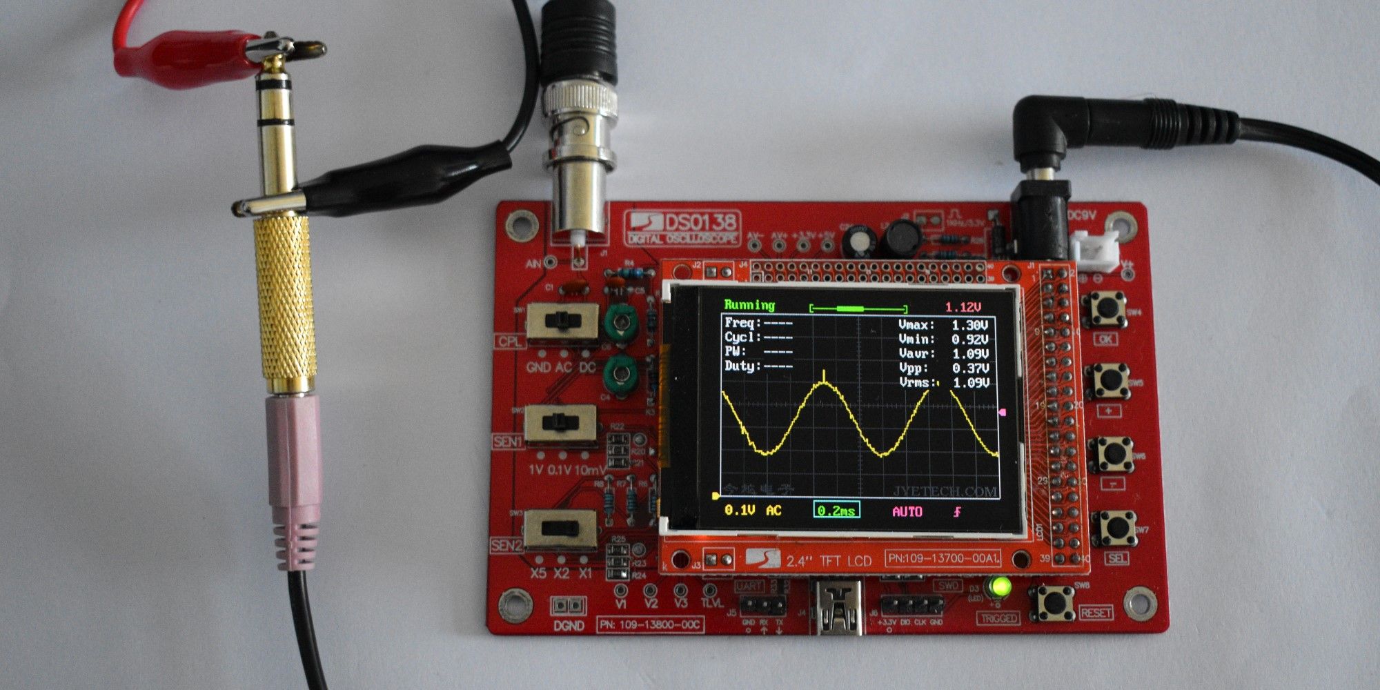
Using your phone and a mini jack-to-jack cable is the easiest and fastest way.
Attach the crocodile clips to the other end of the jack plug.
The big strip around the bottom is the ground, and the other two are left and right.
Pick one, play it, and observe the display.
Here, we’re looking at a sine wave.
You might need to move things around a little to get the waveform centered.
Familiarize yourself with the controls by playing with them.
Zoom in on the waveform, change the trigger level and adjust the timing.
There’s no substitute for getting hands-on!
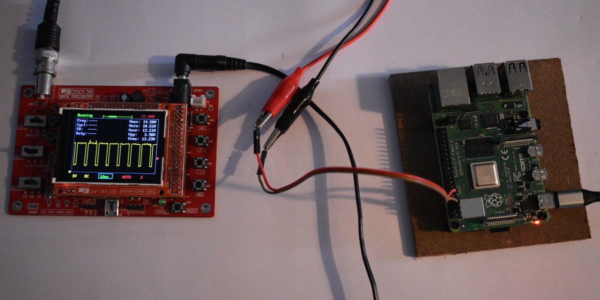
Let’s take a look at what the RPi is actually outputting.
In this case, it’s the PWM pin.
Now, we can run some code.
The PWM signal should appear on the scope.
We can measure the duty cycle and ensure that it matches our expectations.
Software PWM is not particularly stable, especially if the equipment is running other tasks simultaneously.
Often, you might improve your results by simply decreasing the workload on the gear running the program.
Check that possibility before you go any further!
Data Transmission
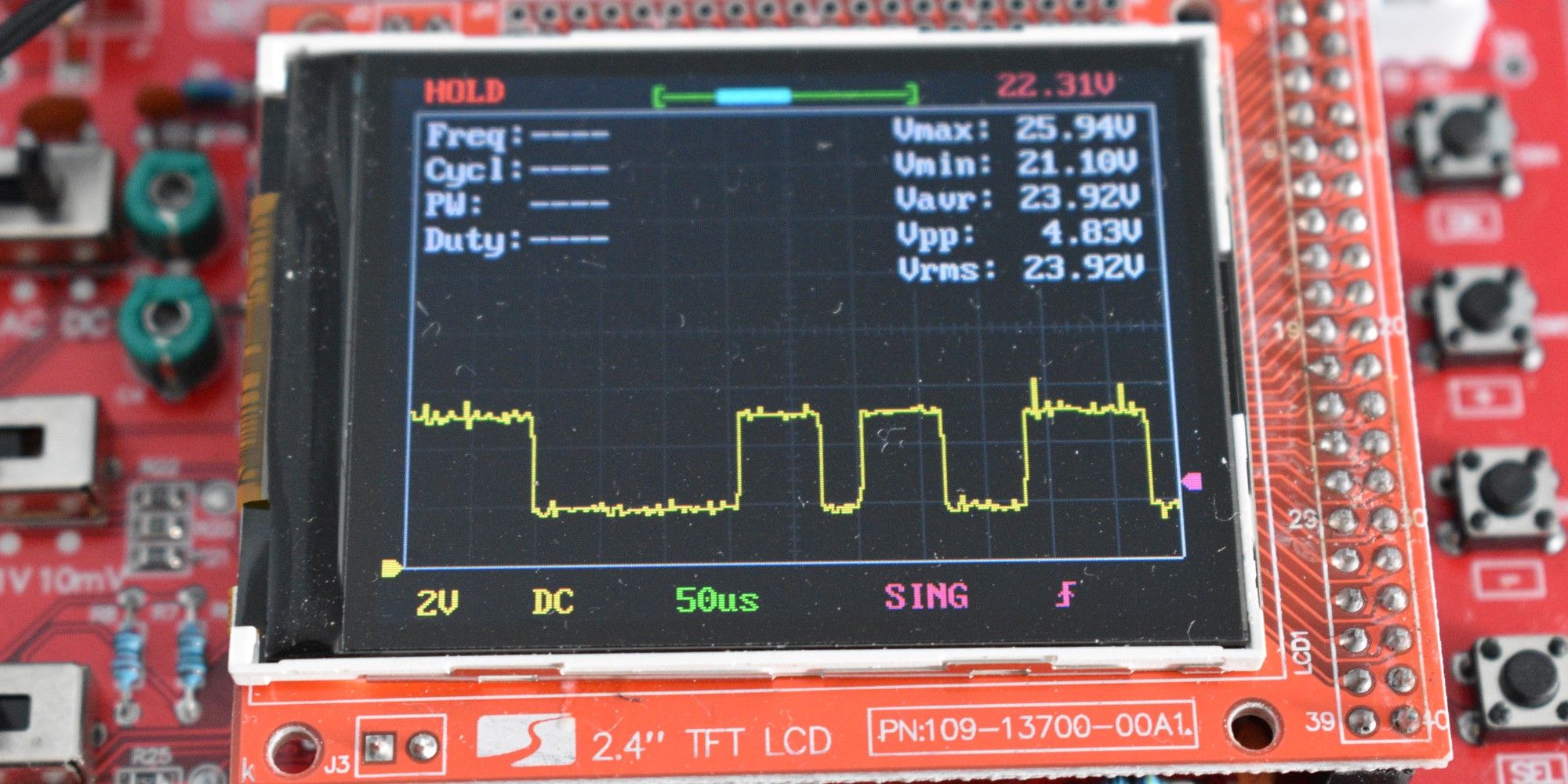
Modern circuitry often relies on signals that aren’t periodic but one-off.
A equipment sends a command to another but doesn’t repeat itself.
To capture these signals, we’ll need to use the one-off functionality of our scope.
Here, the waveform will pause in place when the threshold level is passed.
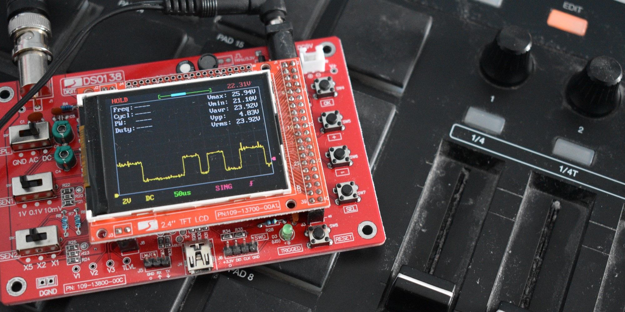
But sincethe cables here are unbalanced, you may have problems if they run beyond a certain length.
This is where deductive troubleshooting comes in!
Zero in on the problem by first checking a different cable and then a different MIDI unit.
Two Signals?
One of the DSO 138’s limitations is that it only allows for one input.
More advanced oscilloscopes might allow us to examine two signals simultaneously.
Doing so might reveal that the two signals are misaligned or distorted.
This will produce garbled data.
Spikes, noise, rounded edgesthese can all cause problems.
Or, we might need a capacitor or two to smooth out the supply voltages.
You might also have to adjust your code to compensate for timing issues.
