DIY solar light projects offer an economical and efficient way to power homes using energy from the sun.
And you might make your own!
We will also incorporate a battery protection circuit to protect the battery from over-discharge.

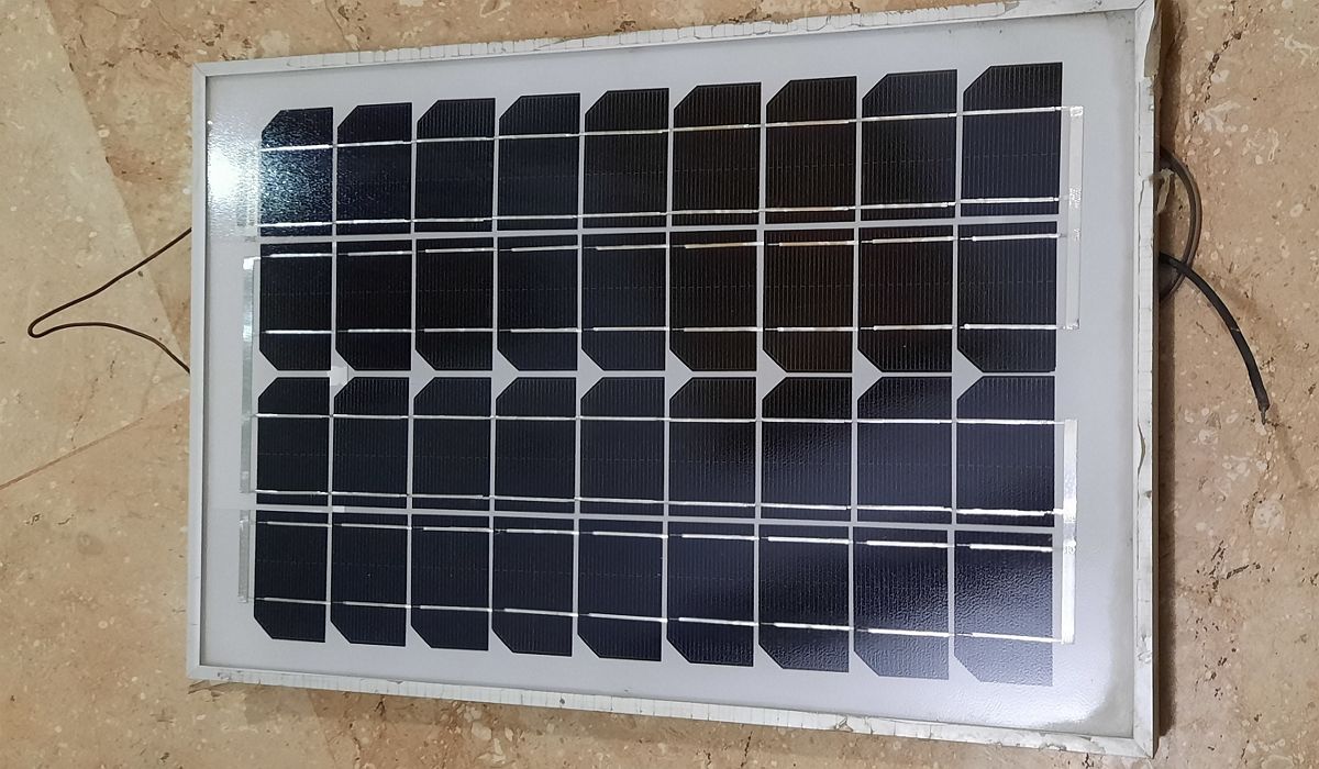
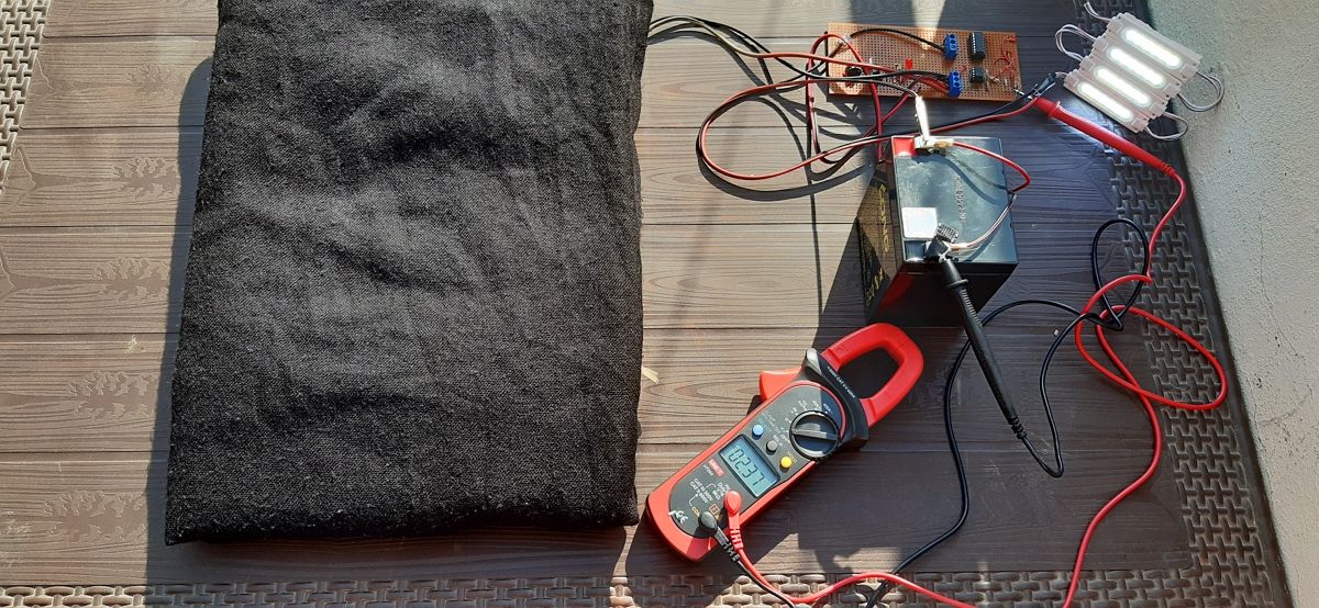
It can charge a 12V battery and can provide 0.62A short circuit current at peak luminosity.
Its physical size is about 12 x 9.
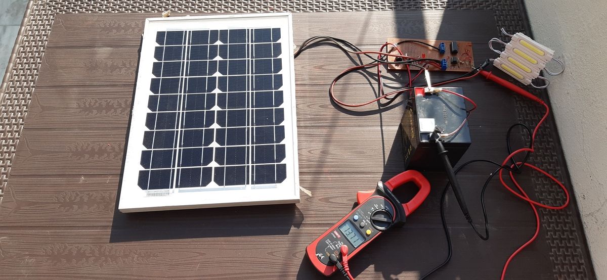
We have used a 12VDC battery with 4Ah current capacity.
During the day, the solar panels generate current which is used to charge the battery.
Black wire (negative polarity) is directly attached to the negative terminal of the battery.
An LED Bulb takes current from the battery.
An electronic circuit controls the bulb using sensor data (solar panel voltage).
Building the Electronic Circuit
The electronic circuit consists of two parts.
Make the electronic circuit for automatic switching and battery drain protection on Veroboard.
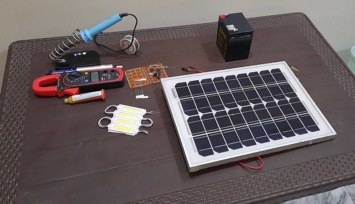
What You’ll Need
The following tools & components will be required for the electronic circuit.
you could get them from online stores likeDigikey,MouserorAli Express.
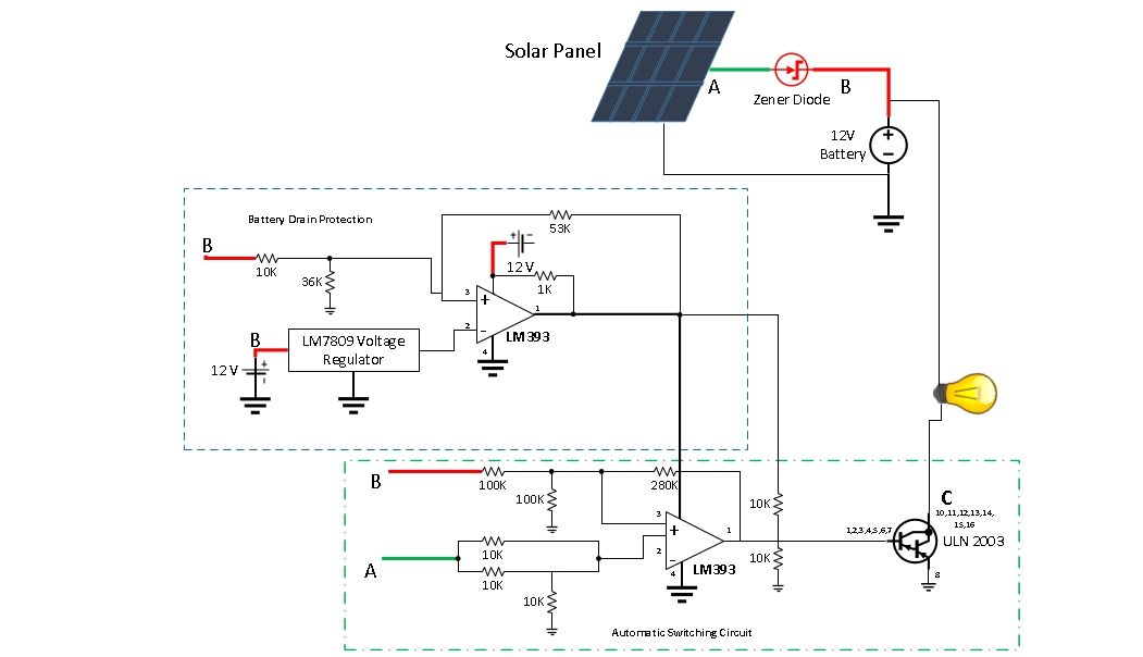
Solar panel and battery are isolated using a Zener diode.
In this circuit, solar panel voltage is compared with battery voltage using a comparator.
When it is greater (during daylight), it gives the signal for switching off the light.
When it is lesser, it signals to switch on the light.
LED bulb is controlled using this logic and with the help of ULN2003 Darlington pair transistors.
ULN2003 gets input from comparator output.
If it gets the signal for On at input pins (1-7) of ULN2003 (i.e.
To make this circuit,join all the circuit elements on Veroboard through soldering.
Schmitt trigger (positive feedback at comparator) is implemented on the LM393 comparator to avoid glitches.
For reference voltage, the LM7809 voltage regulator is used, which takes battery voltage (i.e.
11 to 14 VDC) as input and outputs constant 9V.
To check that the battery doesn’t go beyond deep discharge level i.e.
~11V, use the comparator as a Schmitt trigger.
To unlock the switching circuit again, full recharge of battery to 13.2V is required.
For the battery protection circuit, connect the circuit elements on the Vero board by soldering.
You will find out that the solar panel voltage is higher than the battery voltage.
