Summary
Out of the box, the Raspberry Pi lacks an analog input.
This puts it at a disadvantage compared to microcontroller-based boards like the Arduino.
But dont despair: there are plenty of options to consider.
Get up and running with Raspberry Pi and an external ADC.
Why Add Inputs?
The possibilities are, more or less, limitless.
Options for ADCs
So, which ADC is best for beginners?
Among the most popular and straightforward options are theMCP3004(andMCP3008) chips from Microchip.
So, theres a tradeoff between speed and precision (and, naturally, price).
This is what allows the Arduino to provide analog inputs where the Raspberry Pi cant.
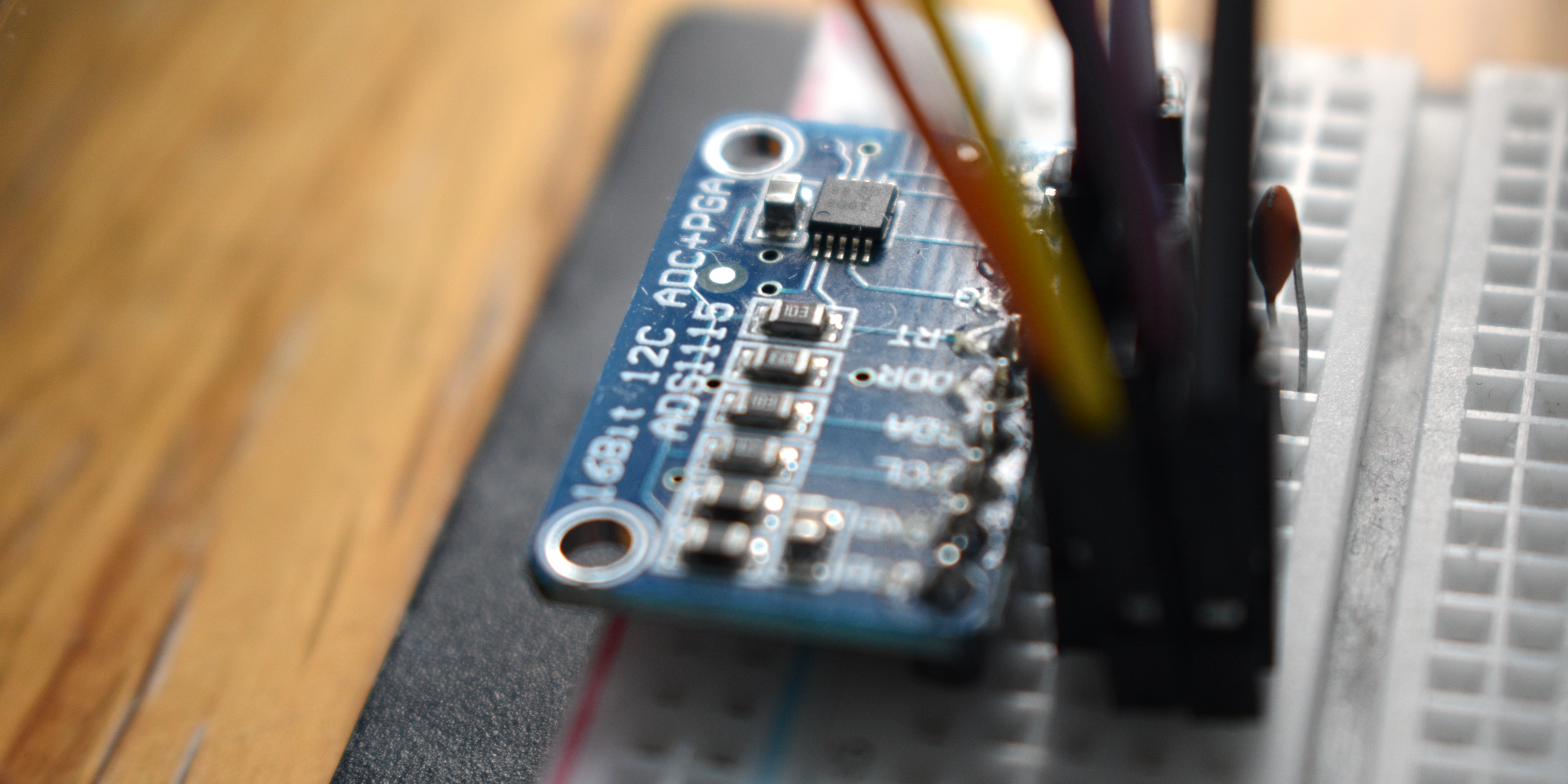
Here, well keep it simple, with an ADS1115 from Adafruit.
What Is a Programmable Gain Amplifier?
This chip comes with a few interesting features, including a Programmable Gain Amplifier (PGA).
This will let you set the desired range of values digitally, down to a fraction of a volt.
The advantage here is that you’re free to change the gain midway through the program.
What About Multiplexing?
A multiplexer (or mux) is a switch that lets you read many inputs using a single ADC.
If your ADC chip comes with many input pins, then theres some internal multiplexing going on.
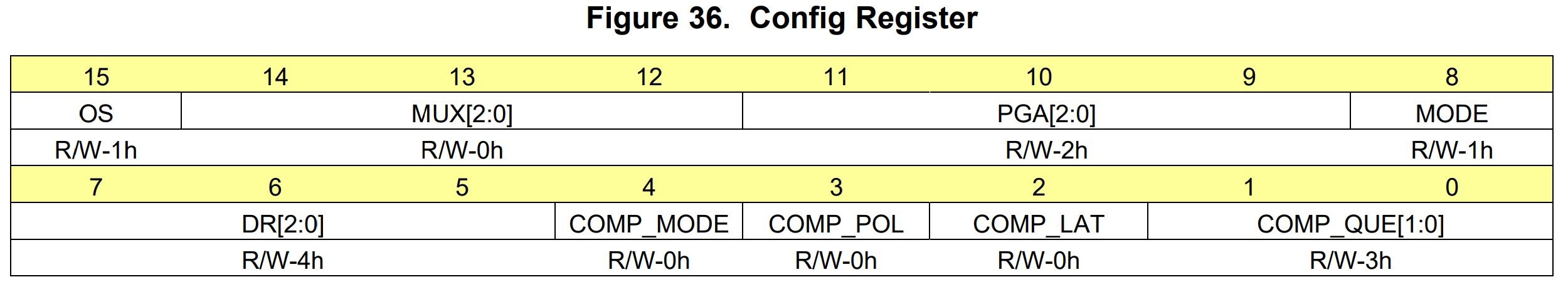
Dealing With Registers
The ADS1115 provides these options, and a few more besides.
But where are those switches?
Theyre inside the package, in the form of very small bits of memory calledregisters.
For example, bits 14 to 12 control the multiplexer.
Using these three bits, you could select from eight configurations.
The one youll want here is 100, which will give the difference between input zero and ground.
Bits 7 to 5, on the other hand, govern the sample rate.
If you want the maximum of 860 samples per second, you could set these to 111.
Once you know which options to set, youll have two bytes to send to the ADC.
Heres where it might get confusing.
In this case, the binary isnt representing a value, but the values of individual switches.
You could express these variables as one big number, in decimal or in hexadecimal.
Wiring It Up
it’s possible for you to plug this equipment straight into the breadboard.
Thats all it’s crucial that you get going!
Dealing With I2C
Different ADCs work via different protocols.
In the case of our ADS1115,were going to be using I2C.
The following example will interact with the ADC using Python.
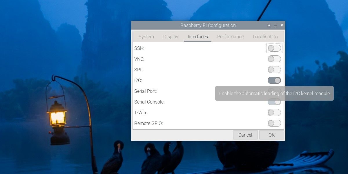
But before you do that, youll need to set it up.
Recent versions of Raspberry Pi OS have made this very simple.
Head toPreferences > Raspberry Pi Configuration.
Then, from theInterfacestab, switchI2Con.
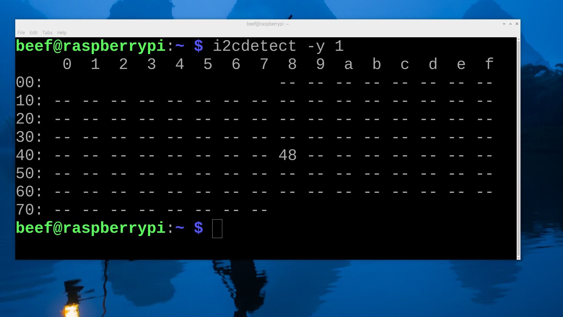
To check everything is working, open a terminal and run:
This command will output a grid.
This is the address of your ADC.
Youll be dealing with two methods here.
The second isread_word_data(), which accepts just the gadget address and the register.
The ADC will be continuously reading voltages and storing the result in the conversion register.
With this method, you’re free to retrieve the contents of that register.
it’s possible for you to beautify the result a little bit, and then print it.
Before you go back to the start of the loop, introduce a short delay.
This will ensure youre not overwhelmed with data.
Youre just about done.
The value of your potentiometer can make a difference, too.
There are also software options.
You might create a rolling average, or simply disregard small changes.
The downside there is that extra code will impose a computational cost.
So, why not take things further?
Tie multiple potentiometers together, or try reading light, sound, or temperature.
Expand the controller youve just made, and create a Raspberry Pi setup thats truly hands-on!
